


 Common Rail Nozzles

Name: Lucy
Tel: +86-13312154946
E-mail: info@ystinjectors.com
Add: Jinyuan Building, 57 Hubin South Road, Xiamen, Fujian
Skype: yistong-cr@hotmail.com
whatsapp: 8613312154946


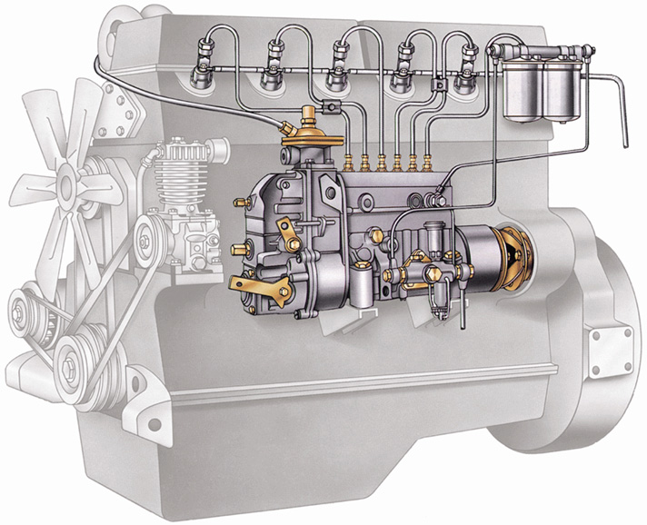
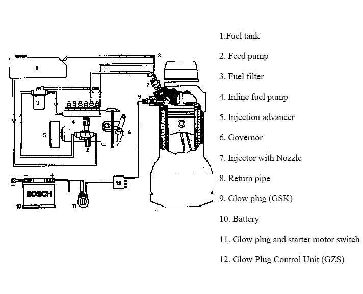
It consists of a fuel supply device, an air supply device, a mixed gas forming device, and an exhaust gas discharge device.
The fuel supply device includes: a diesel tank, a diesel filter, a low pressure oil pipe, a feed pump, a fuel injection pump, a high pressure oil pipe, and a return oil pipe.
The air supply device includes an air filter, an intake pipe, and an intake port in the cylinder.
Mixed gas forming device: combustion chamber.
Exhaust gas discharge device: consists of exhaust pipe, exhaust pipe and exhaust muffler in the cylinder.
Function: Regularly and quantitatively deliver high-pressure fuel to the injector.
Requirements:
1. The order of oil supply is consistent with the order of ignition.
2. The oil supply of each cylinder is uniform (the unevenness is not more than 3%-4%).
3. The advance angle of the oil supply of each cylinder is the same (the difference is no more than 0.5° crank angle).
4. The fuel supply duration is equal.
5. The establishment of oil pressure and the stopping of oil supply must be rapid to prevent dripping.
Inline fuel injection system characteristic parameters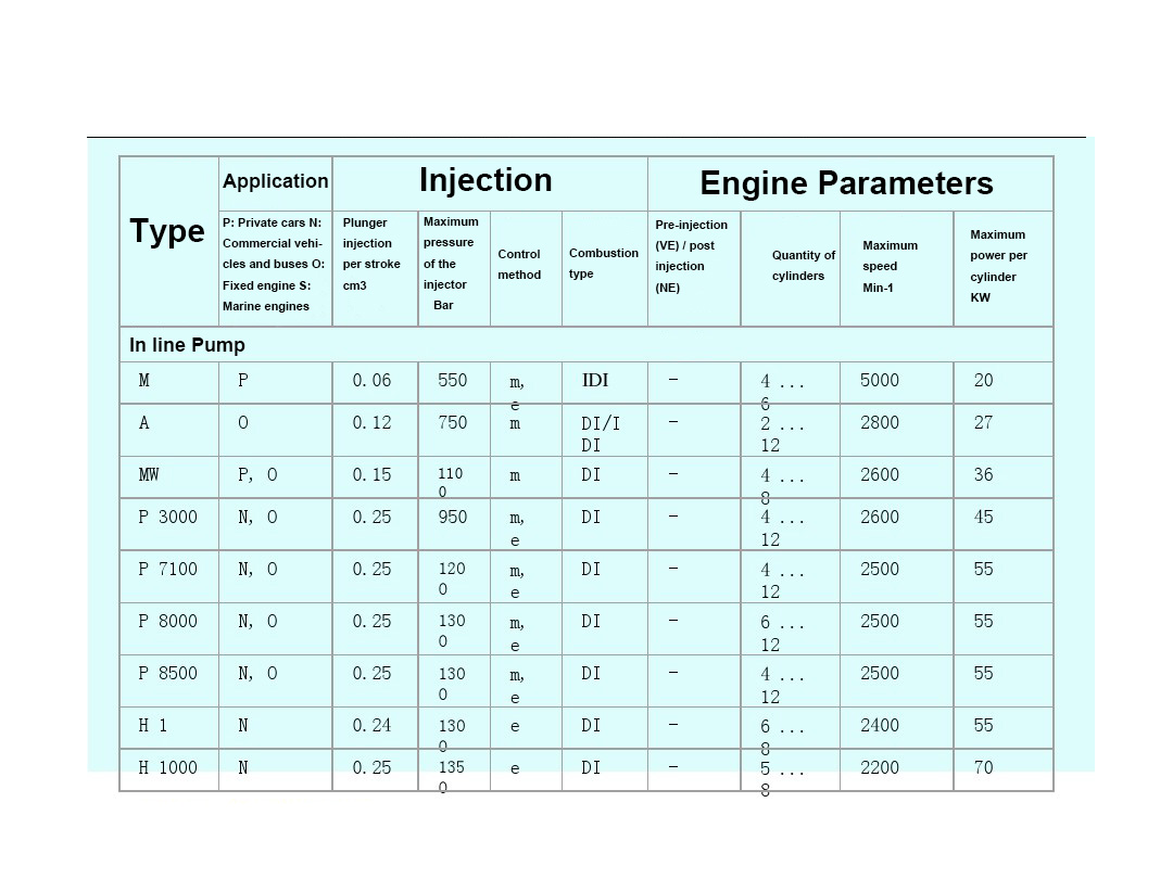
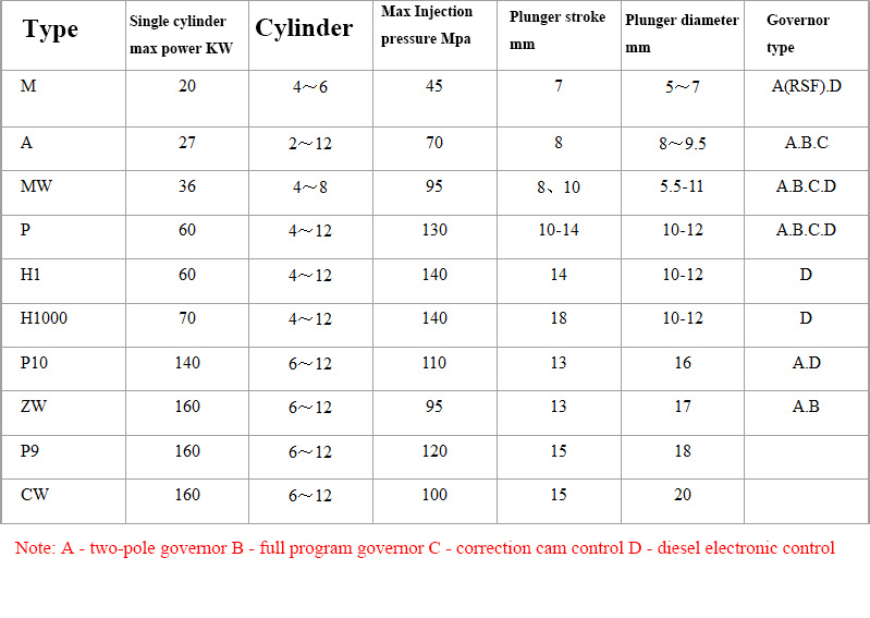
In line fuel injection pump structural parameters
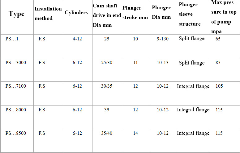
P type Pump specifications
Pipe line layout of the fuel supply system

Injection system for mechanically adjustable inline pump
Feed pump - structure and function
Feed pump - working process
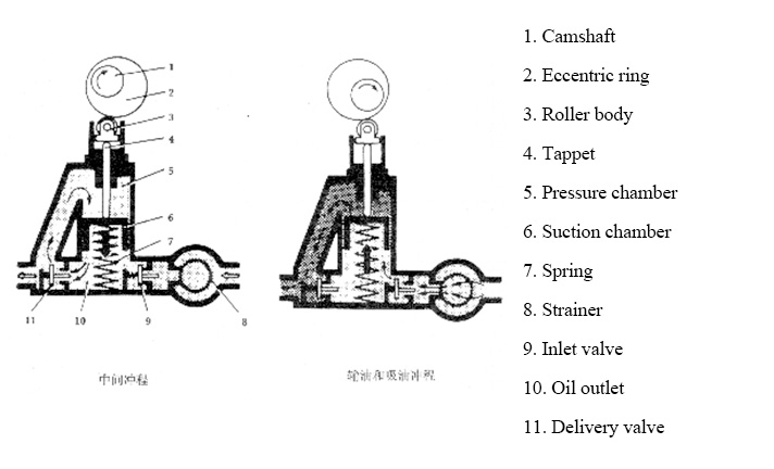
Intermediate stroke:
When the eccentric ring protrusion pushes the tappet, the elastic force of the plunger spring is overcome to make the plunger descend. At this time, the oil pressure in the suction chamber is increased, the inlet valve is closed, and the outlet valve is opened. As the volume of the pressure chamber increases, the fuel in the suction chamber flows into the pressure chamber through the oil passage.
Oil delivery ~ oil absorption stroke:
When the eccentric ring projection is turned, the plunger moves upward under the action of the plunger spring. At this time, the pressure in the pressure chamber is increased, the oil discharge valve is closed, and the fuel flows through the oil passage to the filter.
At the same time, as the volume of the suction chamber increases, the inlet valve opens and fuel enters the suction chamber.
Fuel Filter
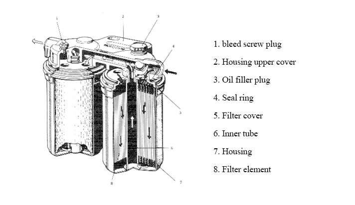
The life of a fuel injection system depends to a large extent on the quality of the fuel filter and the maintenance of the fuel filter. The precision parts of the injection device (plunger, delivery valve, needle valve) have strictly matching clearance, generally around 0.003mm. This means that if the size of the impurity particles in the fuel is smaller than the gap size, these parts can work normally. Failure to do so may result in abnormal wear of these parts, resulting in abnormal engine combustion, increased fuel consumption, difficulty in starting, rough idling, and reduced engine power. For this purpose, special fuel filters are installed in the low-pressure oil circuit according to the requirements of the vertical pump.
Vertical pump construction
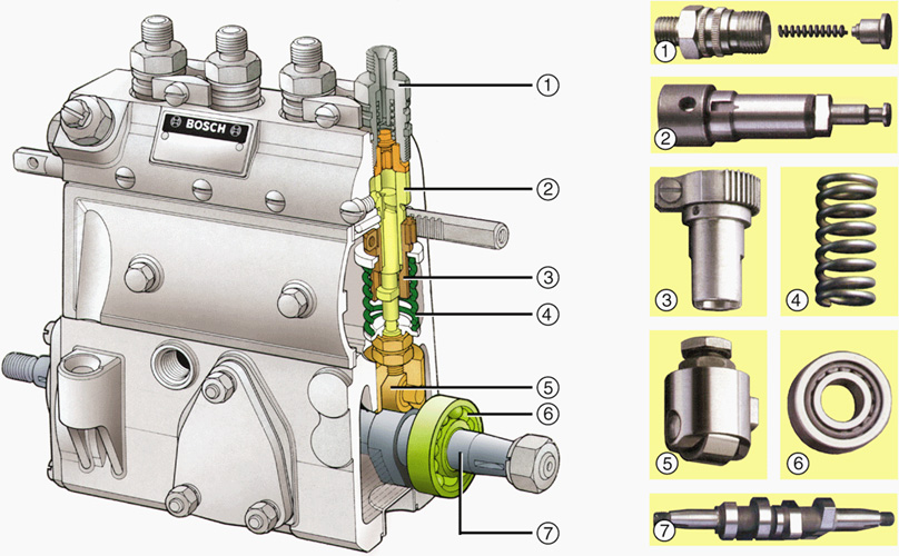
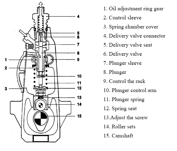
Vertical pump construction – plunger/elements
Plunger spiral chute form:
Lower spiral groove type: the plunger whose oil supply starting point is unchanged and the oil supply end point is changed.
Upper spiral groove type: the plunger whose oil supply start point changes and the oil supply end point does not change.
Up and down spiral groove: a plunger that changes both the start and end points of the oil supply.
. The spiral chute is divided according to the direction in which it is inclined:
Left-handed: After placing the plunger in the vertical position, observe the direction in which the chute rises. If the chute rises to the left, it is left-handed.
Right-handed: After placing the plunger in the vertical position, observe the direction in which the chute rises. If the chute rises to the right, it is right-handed.
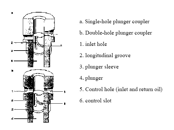
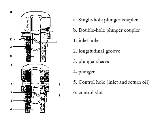
Plunger with leaking oil return
If the fuel injection pump is connected to the engine's lubricating oil system, it may cause dilution of the lubricating oil due to fuel leakage. If the plunger coupler leading to the fuel injection chamber of the fuel injection pump is installed in the leaking oil return tank, this kind of event will be avoided.
a 1. Leak back to the oil sump 2. Ring groove
b 1. in the plunger leaks back to the oil hole 2. Ring groove in the plunger sleeve
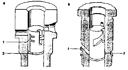
For some engine specific requirements, such as reducing noise or harmful substances in the exhaust, it is necessary to provide a starting time for fuel supply that varies with load. The oil pump plunger makes it possible to advance the load-related oil supply by means of additional control slots at the upper and lower ends. To improve the starting performance of some engines, an oil pump plunger with a starter slot can also be used.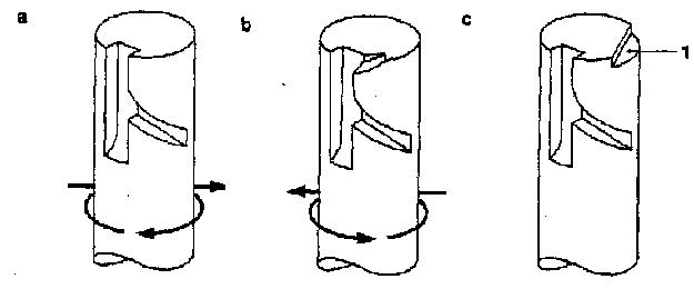
a. the lower control slot b. the upper and lower control slots c. the lower control slot, with the starter slot
Delivery valve
Function
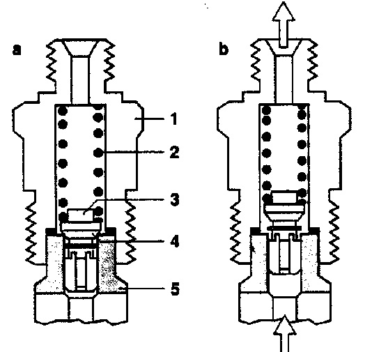
The basic function of the delivery valve is to cut off the high pressure circuit between the high pressure oil pipe and the oil pump plunger, and reduce the pressure in the high pressure oil pipe and the nozzle to a given static pressure after the injection. The reduced pressure allows the injector to close quickly and accurately while avoiding grease dripping.
a. closed b. during oil supply
1. Delivery valve joint 2. Delivery valve spring 3.Delivery valve 4.Delivery valve seat surface 5 .Delivery valve seat
Working process
During the oil supply, the pressure generated in the high pressure chamber lifts the valve body of the delivery valve away from the seat surface. At this time, the fuel is delivered to the injector through the delivery valve joint and the high pressure oil pipe. When the control tank in the oil pump plunger stops supplying oil, the pressure in the high pressure chamber will drop, and the valve body will be pulled back to its seat surface due to the action of the delivery valve spring. The space between the oil pump plunger and the high pressure circuit will be cut off until the start of the next effective oil supply stroke.
Isometric valve without return oil throttle
a. common type b. with correction
1. delivery valve seat surface, 2. Decompession belt, 3 annular groove 4 outlet valve guide surface, 5. longitudinal groove 6. Processed grinding surface
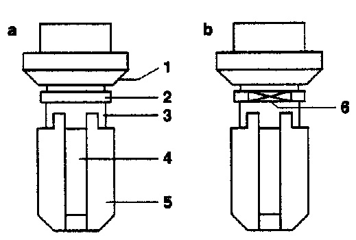 A part of the valve stem in the isovolumetric valve is formed in the shape of a piston (pressure reducing belt) which is coupled with the pilot hole in the delivery valve with a very small gap. When the control groove of the plunger stops the delivery of the fuel, the delivery valve is closed under the action of the spring force, and the pressure reducing ring belt enters the pilot hole of the delivery valve, thereby closing the passage between the high pressure chamber and the high pressure oil pipe. . At the same time, the pressure reducing ring has a stroke volume added to the high pressure oil pipe.
In order to obtain the required fuel supply characteristic curve, a calibration valve can be used in some special cases.
Isometric and equal pressure valves with oil return throttle
Isometric valve with return oil throttle
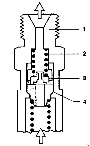
The oil return throttle valve can be additionally used on the isovolumetric valve. Its function is to reduce the vibration caused by the oil pressure wave generated when the nozzle is closed, so that it does not damage other components. This can reduce or even completely avoid the effects of wear and air corrosion
1. Delivery valve connector 2. Delivery valve spring 3. orifice valve 4. seat
Isobaric valve
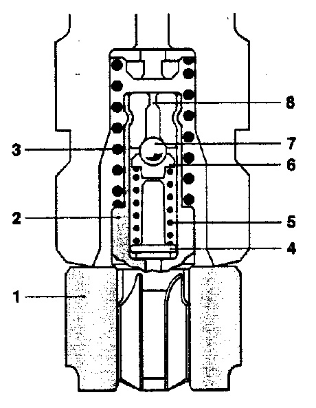
The isobaric valve is composed of a pre-delivery valve in the oil supply direction and a stabilizing throttle valve in the return direction. The regulated throttle valve keeps the static pressure in the high pressure fuel line as stable as possible under any operating conditions. The advantage of the isobaric valve is that it avoids the corrosive effect of the air and improves the stability of the hydraulic pressure. The isobaric valve can be used for high pressure fuel injection pumps (above 800 bar) and small high speed direct injection fuel injection pumps.
1. seat 2. cone 3. Delivery valve spring 4. volume reduction body 5. pressure valve 6. spring seat 7.sphere 8. resistance channel
Cam Disk profile
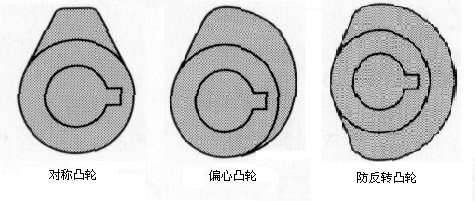
Due to the difference between the combustion system and the shape of the combustion, there are different requirements for the injection conditions. That is to say, for any kind of engine, there must be a matching injection process. The speed of the plunger, and the associated injection duration, is determined by the cam stroke associated with the cam angle. It is for this reason that different shapes of cams have appeared in practical applications. In order to improve the injection conditions, such as the curve at the time of injection, and the load of the pressure, etc., a specially shaped cam that has been calculated and designed can be used.
Plunger-Type Fuel Pump with oil supply process
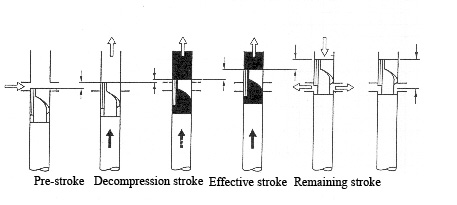
Pre-stroke The distance the plunger moves from bottom dead center to its upper end face when the oil inlet hole is completely closed. It is determined by the engine's requirements for the fuel supply advance angle.
Decompression stroke The distance the plunger rises from the end of the pre-stroke to the time when the relief valve decompression ring starts to leave the pilot hole of the valve seat. It is determined by the size of the cylindrical ring on the delivery valve.
Effective stroke The plunger is lifted from the time the oil outlet valve opens to the edge of the plunger spiral chute opening the oil return hole. It determines the power of the associated engine (ie, the amount of fuel supplied) and the diameter of the plunger.
Remaining stroke The distance it rises from the end of the effective stroke to the point at which the plunger reaches the dead center. It is the transition stroke necessary to reduce the parts of the plunger, roller body assembly, etc. from maximum speed to zero.
Vertical pump working principle –Fuel-flow control
Using the lever control
a. Zero oil supply b. Partial oil supply c. Maximum oil supply
1. Plunger sleeve 2. Oil inlet hole 3. Plunger 4. Control groove 5. Control gear rod
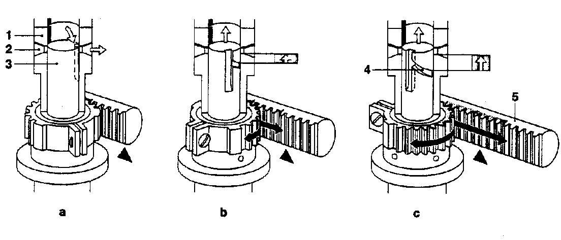
Use the joystick control
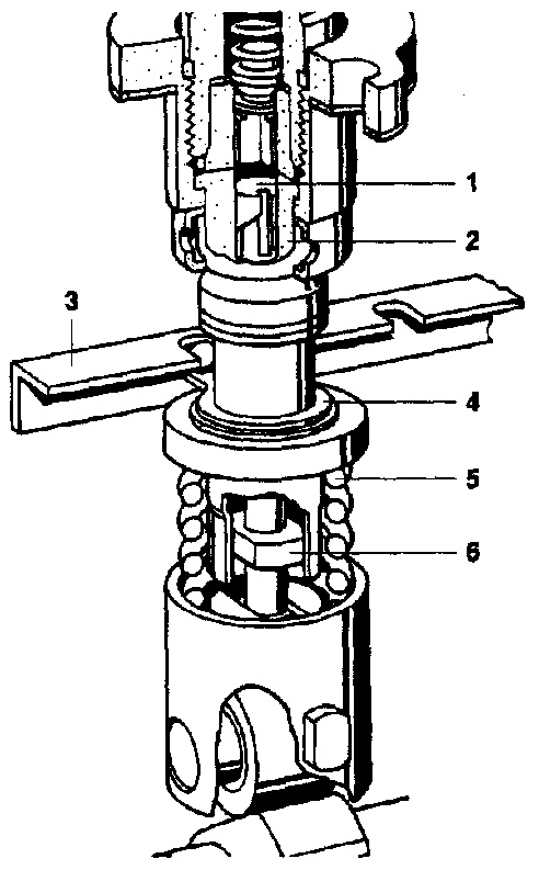
1. plunger 2. plunger sleeve 3. lever 4. oil control sleeve 5. plunger spring 6. plunger control arm
The principle of fuel-flow control: the control rod rotates the plunger through the oil control sleeve, and the effective stroke of the plunger can be changed to adjust the oil supply amount of each cycle.
Fuel pump adjustment
1. Pre-stroke adjustment: By adjusting the adjustment of the plunger stroke at the start of oil supply, the working section of the cam type is selected to ensure the injection pattern of the fuel injection pump;
2. Adjustment of the fuel supply amount: The oil supply amount required for the engine power is ensured by setting the rotation speed and the adjustment of the fuel supply amount under the given rack stroke.

